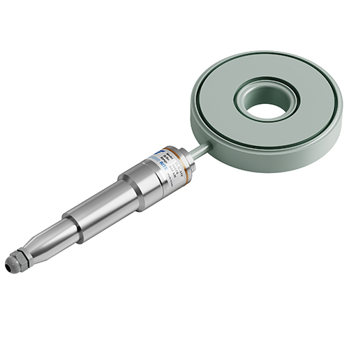
Encardio Rite Model ELC-31V is a vibrating wire load cell with a hydraulic centre hole uniquely designed to be applied during rigorous environments associated with civil engineering applications and construction activity.
A vibrating wire load cell presides over a conventional electrical strain gauge or semiconductor-type load cell through its usage of frequency as an output signal, as opposed to using voltage.
The use of this load cell allows transmitting frequency by over 1km of cable length without finding disruptions from water penetration, temperature fluctuations, contact resistance or leakage to ground. It finds its application in series with a hydraulic jack for applying load. Consequently, it verifies the load as applied by the hydraulic jack.

One of the main concerns of geologists, design engineers, and Construction Companies is the falling of the roof or sidewall in underground cavities which causes great disruption of life, property, money, and time.
Natural disasters like slope falling, landslides, roof collapsing, etc. can happen anywhere in the world. Preventive measures and corrective actions are taken to ensure that there is minimal threat to life and property. One such method is anchoring.
Anchoring has found its way as a very useful and important preventive method. It reduces the above-mentioned disasters by the usage of pre-stressed grouted anchors providing an effective support system. In any optimum, safe and economic use of anchoring, anchor spacing and anchor load have to be determined. This is implemented by the usage of a centre-hole vibrating wire load cell and a suitable readout unit. In those cases where multiple sensors are installed, a data logger may also be used to make the study and analysis easier.
Vibrating Wire Load Cell – General Description
Encardio Rite ELC 31-V Vibrating Wire Load Cell is built from stainless steel and is fluid-filled, varying in capacities from 500 kN to 2000 kN. Load cells with different internal diameters can be arranged on request. Apart from that, a 2500kN load cell without a Centre hole is also available.
Read more: Centre Hole Load Cell Installation: Preparation & Troubleshooting

The Vibrating Wire Centre Hole Load Cell is constructed using a sensitive pressure pad which is created by welding together two stiff steel discs at their periphery. De-aired fluid fills the space inside the load cell.
The load cell works by monitoring the pressure on the fluid as any load applied to the cell is reflected in the fluid. Change in fluid pressure is then used to observe the variation in the load being applied to the cell. Using a think-load distribution plate, the load is distributed equally over the loading area.
| Capacity kN | ELC-31V Vibrating Wire Centre Hole Load Cell |
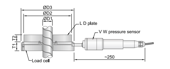
| T1 mm | D1 mm | D2 mm | D3 mm | Weight kg |
| 500 | 28 | 52 | 144 | 160 | 4.5 |
| 750 | 28 | 78 | 180 | 196 | 6 |
| 1000 | 28 | 105 | 219 | 235 | 8 |
| 1500 | 28 | 105 | 249 | 265 | 11 |
| 2000 | 30 | 130 | 265 | 281 | 12 |
| 2500 | 30 | 0 | 260 | 281 | 15 |
| Capacity kN | Load Distribution/Bearing Plate |
| OD mm | ID mm | T2 mm | Wt.kg |
| 500 | 144 | 52 | 33 | 4 |
| 750 | 180 | 78 | 33 | 6 |
| 1000 | 219 | 105 | 38 | 9 |
| 1500 | 249 | 105 | 38 | 12 |
| 2000 | 260 | 130 | 48 | 16 |
| 2500 | 260 | – | 48 | 20 |
Making use of a vibrating wire pressure transducer, the fluid pressure inside the load cell is measured. The pressure transducer is formulated with stainless steel and makes use of the latest vibrating wire technology that provides electrical read-out. For a smooth cable connection, a glass-to-metal seal is incorporated. A thermistor is included in the pressure sensor for monitoring temperature.
There is a tri-polar plasma surge arrestor included inside the pressure transducer housing that shields the vibrating wire pluck and read coils from electrical transients such as may be induced by direct or indirect lightning strikes.
Cables from the coil magnet conclude on the glass to metal seal which in turn is an electron beam welded to the stainless steel body of the pressure sensor. The red and black pin is connected to the coil magnet. The other pins are connected to a thermistor. A cable joint housing and cable gland are provided for the cable connection.
In most cases, the load cell is provided without any cable attached to it. Cable jointing with the required length of appropriate cable can be easily done at the site. A required length of cable can be provided if requested.
Read more: Strain Gauge Type Load Cell- Introduction & How it Works?
Load distribution plates can be placed above and below the load cell to ensure an even distribution of load on the sensor. The load distribution plate on the bottom of the load cell is not usually required if an adequate bearing plate has been incorporated into the proposed installation arrangement.
Vibrating Wire Load Cell – Operating Principle
The vibrating wire pressure cell of the load cell consists of a magnetic, high tensile strength stretched wire, one end of which is attached and the other end fixed to a diaphragm that turns in proportion to applied pressure.
A slight change in pressure reflects on the diaphragm proportionally which in turn affects the tension in the stretched wire. Thus, any change in load directly affects the tension in the wire.
Read more: Strain Gage Type Compression Load Cell Installation Procedure
The wire is plucked by a coil magnet. Proportionate to the tension in the wire, it resonates at a frequency ‘f’, which can be determined as follows:
f = [σg/ρ] 1/2/ 2l Hz
Where σ = tension of wire in kg/cm2
g = 980 cm/sec2
ρ = density of wire in kg/cm3
l = length of wire in cm
The resonant frequency of the vibrating wire leads to an alternating current in the coil magnet. The load is proportional to the square of the frequency and the readout unit can display this directly in engineering units.