Old monuments or structures often deteriorate with time and, it’s pretty crucial to carry out routine health check-ups. Structural health monitoring is an important aspect of geotechnical monitoring and, it utilizes various instruments for the same.
A tiltmeter is one such instrument that is designed to monitor the amount of deflection or tilt in a structure. While tiltmeters can be of various types, here is everything that you need to know about El Tiltmeters – how they operate, how are they installed and what are its applications.
What are El Tiltmeters?
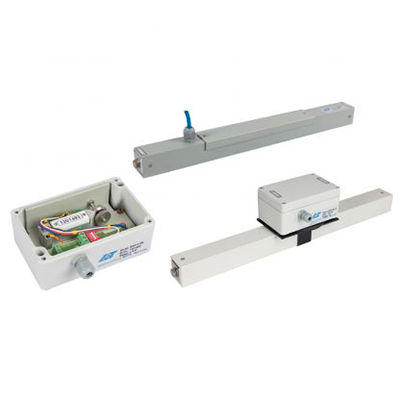
Electrolytic level-type tilt meters are used to measure a very small amount of tilt. Encardio Rite’s Model EAN-31EL tiltmeter is suitable for monitoring minute changes in inclination and vertical rotation of structure at a point. It is a high-resolution tiltmeter with a rugged construction.
The tilt meter monitors the deflection and deformation of structures such as high-rise buildings, retaining, and diaphragm walls, etc. Tilt changes in structures may be caused due to construction activities such as excavation; tunneling and de-watering that affect the surrounding ground that supports the structure.
Changes in tilt may also take place because of the loading of a dam during impoundment, the loading of a diaphragm wall during excavation, or the loading of a bridge deck due to wind and traffic.
Data from electrolytic tiltmeters provides early warning in case of an emergency so that preventive measures can be taken on time.
The Encardio Rite Model EAN-31EL tiltmeter is contained by an aluminum die-cast enclosure and is generally used as a standalone unit for measuring tilt. It is either installed directly on the structure whose tilt is to be monitored (using mounting brackets) or fixed to horizontal or vertical beams.
The Model EAN-31EL, electrolytic tiltmeter can be mounted on 38 mm x 38 mm hollow square aluminum structural sections (beam). The length of the beam is known as the gauge length and is supplied with suitable mounting hardware for fixing concrete or brickwork structures.
The beam-mounted tilt sensor measures the tilt angle between the endpoints of the beam. From the measured tilt angle and the beam length, the vertical or horizontal displacement (depending on the orientation of the beam) of the endpoints of the beam can be precisely calculated.
The Encardio Rite Model EAN-31EL-B beam sensor is an EAN-31EL tilt meter mounted on a beam of specified gauge length and suitable mounting hardware for fixing the beams to the structure.
The beams are available in different standard lengths, generally between 1 to 3 meters. The beam sensors are often used as a linear array of linked beams, fixed to anchors at specified lengths. An array of linked beam sensors allows the vertical settlement profile along the array line to be determined.
El Tiltmeters – Operating Principle
The El tiltmeter utilizes a bubble level sensor similar to the one used in spirit levels. The only exception is that in this case the spirit is replaced with an electrically conductive fluid known as an electrolyte.
In EAN-31EL, the glass vial of the spirit level is replaced with a more thermally stable and dimensionally accurate ceramic housing. The ceramic electrolytic bubble level sensor has three terminals and acts as a resistive half-bridge circuit.
The electrolytic bubble sensor has two end terminals and a middle terminal. Electrically it appears as a potentiometer with a fixed resistance between its end terminals while the middle terminal behaves as a wiper in a potentiometer.
When the bubble level tilts, the resistance between the middle and one of the end terminals goes up while it goes down between the middle and the other end terminal. The effect reverses if the direction of the tilt is reversed.
The variation in the ratio of resistance between the middle terminal and the two end terminals can be measured using an electrical half-bridge circuit. In a half-bridge circuit, the indicator/data logger applies a voltage across the end terminals and measures the output voltage between the middle terminal and one of the end terminals. Unfortunately, as the electrolyte used in the sensor deteriorates irreversibly (if a DC voltage is applied across its terminals), a pure AC excitation voltage source is a must.
In El tilt sensors with raw output option, the bubble level sensor terminals are directly available across the output terminals. Whereas, in tiltmeters and beam sensors with voltage output option, a signal conditioning card converts the half-bridge bubble level sensor output to a proportional DC voltage with a nominal full-scale value of ± 1 V DC.
Tilt sensors with a measurement range lower than 1° are very sensitive sensors and are easily influenced by even small vibrations that appear as noise on the output.
These sensors should, as far as possible, be mounted at locations where expected vibration levels are quite low. To exploit the full sensitivity limit of these sensors, some kind of averaging facility should be available in the readout unit or data logger used for monitoring.
| Read More: What Are Tiltmeters And Where Are They Used? |
How are El Tiltmeters Installed?
The electrolytic tiltmeter Model EAN-31EL is housed in a weatherproof die-cast aluminum box and can be fixed to any structure either directly using 4 mounting screws/fasteners or a mounting kit that allows more flexibility.
The beam sensor model EAN-31EL-B consists of an EAN-31EL tiltmeter together with a 38mm x 38mm square hollow aluminum structural section (beam) of a specified length. The tiltmeter may be factory-fitted on a beam or the two can be supplied separately for assembly at the site. Standard beam lengths are 1m, 2m, and 3m but customer-specified beam lengths between 0.5 m to 3m are also supplied.
The beam length in the specification refers to the gauge length of the beam in the mounted position. The actual length of the beam is about 36 mm longer than the specified size due to the mounting brackets provided at the end of the beams.
The beams can be fixed either horizontally or vertically as desired depending on the kind of tilt to be measured. The sensor mounting bracket on the beam allows the tiltmeter to be rotated by 90º so that the tiltmeter can be mounted in a horizontal position, irrespective of the orientation of the beam.
El-Tiltmeter Mounting Kit
The tiltmeter and the beam sensors can be mounted directly to the anchors on the wall or floor using the mounting angles or brackets supplied. However, if the structure is likely to deform in directions other than the rotational plane of the beams, the use of components supplied in the optionally available mounting kit will give precise results.
A couple of mounting kits are required for mounting an individual beam sensor.
Each mounting kit consists of a set of groutable 148 mm long all-threaded stud anchors, with an angle bracket and a set of nuts, spring washers, and plain washers. Another set of an all-thread stud anchor of around 72 mm length and a set of nuts, plain washers, spring washers, disc spring washers, two single-shouldered and one double-shouldered nylon washer is also included.
The nuts and washers supplied are assembled on the respective studs from which the correct position of these components during assembly can be noted.
El Tiltmeter Installation Procedure
The EAN-31EL Tiltmeter is used to measure the simple rotation of structures in a single plane known as the plane of rotation. The plane of rotation is the one that is parallel to the backside (surface) of the tiltmeter.
Depending on the monitoring requirement, the tiltmeter can be mounted in two different ways as described below.
Rotation expected in the plane of the wall
If the structural rotation is expected to be in the plane of the surface of the wall, the tiltmeter is mounted directly on the wall using the wall-mounting bracket. The use of a wall mounting bracket allows coarse leveling of the tiltmeter and the alignment of the anchors need not be very precise.
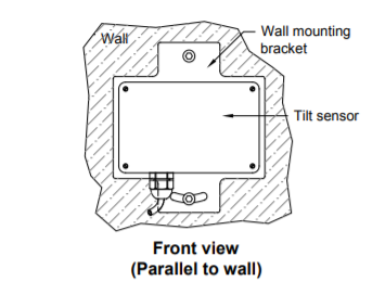
The wall mounting bracket is fixed to the wall using any commercially available 8 mm anchors/fasteners suitable for brick or concrete walls.
- Using the wall mounting bracket as a template, mark the position of two mounting holes.
- Visually ensure that the two-hole positions are aligned vertically as much as possible.
- Drill two holes of diameter and depth suitable for the type of anchor to be used.
- Fix the mounting anchors in holes following the manufacturer’s recommendation.
- Mount the tiltmeter on the wall-mounting bracket.
- Fix the wall-mounting bracket with the tiltmeter to the anchors on the wall.
Rotation expected in a vertical plane perpendicular to the wall
If the surface of the wall is expected to rotate in a vertical plane perpendicular to the wall the tiltmeter should be mounted in an orientation as shown in the accompanying figure. The use of a mounting kit is recommended as this allows easy adjustment of the tiltmeter orientation.
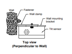
Remove tiltmeter cover. Fix the tiltmeter housing to the mounting bracket using the two mounting screws. Replace tiltmeter cover.
- Drill 12mm diameter anchor holes to a depth of about 100 mm at the marked position.
- Clear the hole of debris by blowing air or brushing.
- Fix the longer (148 mm) anchors of the mounting kits with suitable epoxy grout in these holes such that around 50mm length of anchors project out of the surface after fixing. Follow the epoxy manufacturer’s recommendation for fixing the anchors.
- Allow the grout to set for the recommended time before handling. Fasten angle brackets to the already grouted 148 mm anchors. Check the relative position of the nuts, washers, and angle brackets from the accompanying figure.
- Fix the 72 mm stud anchors on the angle brackets fixed to the grouted anchors.
- Fix the tiltmeter mounting bracket on the 72 mm stud anchors as shown in the accompanying figure.
- Lightly tighten the nuts so that the spring washers are slightly compressed.
- Ensure that the tiltmeter cover surface is both, perpendicular to the wall as well as vertical.
- Put a drop of Loctite 290 (post-assembly thread locking compound) at the accessible junction of each nut on the studs to lock them in place.
Usage of El Tiltmeters
The EAN-31EL tilt sensor is mostly used for standalone applications where only the change in tilt or rotation of the structure is to be measured. The tilt sensor enclosure can be directly mounted on the structure by using two mounting screws or, more often, by using a suitable wall mounting bracket that allows some degree of rotational adjustment to orient the tilt sensor in a true horizontal position. The use of a wall-mounting bracket allows easier drilling of mounting holes as very precise hole locations are not required.
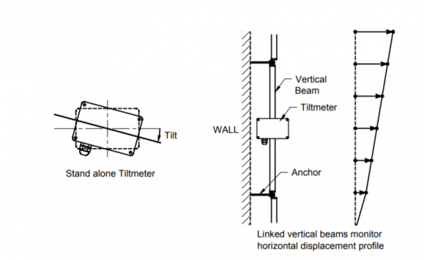
The EAN-31EL tilt sensor is also used with vertical beams of known lengths to determine the horizontal displacement of walls etc. In most cases, a series of linked beams are fixed to the wall vertically using a series of anchors. The distance between the anchors is known as the gauge length. Two adjacent beams in the link share the same anchor.
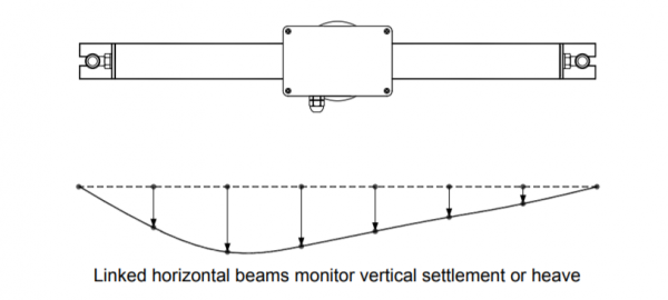
The EAN-31EL-B horizontal beam sensor is primarily used for obtaining the vertical displacement (i.e. settlement or heave) profile. A series of beam sensors are fixed to an array of anchors in a straight line in the desired direction, along which a vertical displacement profile is required. A stand-alone horizontal beam sensor (i.e. when used singly) is equivalent to a simple tiltmeter and offers no additional advantage unless vertical displacement between two anchors at a certain distance is required to be measured.
When beam sensors are used in an array, plotting the individual displacements against the gauge length of each beam yields the displacement profile as shown in the figure below.

Gauge lengths in an array can be mixed, using shorter gauge lengths where higher resolution is required and longer gauge lengths where lower resolution is required or expected displacement values are very low.
However, the use of a uniform gauge length will give satisfactory results for most applications. The sensor beam lengths in the figure are shown as L1, L2,… L7 and the corresponding displacements measured by each sensor are shown above as d1, d2, ..d7.
All beam lengths shown in the figure are equal. The sign of displacement follows the Encardio Rite convention for the EAN-31EL sensors. Displacement of sensors rotating anti-clockwise are shown with a positive sign and displacement of sensors rotating in the clockwise direction are shown with a negative sign. On plotting the cumulative length vs. the cumulative displacement curve, one gets the vertical displacement profile along the line of the sensor string.
Applications of El Tiltmeters
The El Tiltmeters are used:
- To monitor vertical rotation, deflection & deformation of the diaphragm & retaining walls.
- To monitor the inclination and rotation of dams, piers piles, etc.
- To monitor structures for the effects of tunneling and excavation.
- To monitor the stability of structures in landslide areas.
- To monitor tunnels for convergence and other movements.
- To evaluate the performance of bridges & struts under load.
This was all about electrolytic tiltmeters and beam sensors. If you have a suggestion to make or a question to ask, feel free to drop your comments below and, we would love to answer them.